Guide for Packing PEEK HPLC Column Hardware
MICROSOLV does not provide a universal SOP for packing PEEK or stainless‑steel column hardware because every chromatographic phase—silica‑based, polymeric, bonded, core‑shell, or specialty media—requires its own optimized packing procedure. The packing material supplier should always be consulted for phase‑specific slurry concentration, solvent recommendations, compression parameters, and finishing steps.
However, this article provides practical, hardware‑specific guidelines for using ARE-Applied Research brand PEEK HPLC column hardware so you can develop a robust, reproducible packing method that stays within the safe mechanical limits of these systems.
General Packing Principles for PEEK HPLC Columns
Regardless of the phase, ID, or packing method, the following steps define a safe and functional workflow for packing PEEK column bodies:
1. Prepare and close one end of the column (with frit installed)
Install the appropriate PEEK end fitting and frit on the bottom side of the column. This establishes the stationary outlet surface that supports the bed during packing.
2. Connect the open column end to the slurry reservoir
Use only PEEK sealing rings (not frits) in this connection. Frits must never be used between the column and the slurry reservoir because they restrict slurry transfer and can trap particles, creating inhomogeneous packing density or void regions.
3. Orient the assembly vertically
The open side of the slurry reservoir must be upright, with the column below it. This configuration ensures gravity‑aided filling and reduces bubble introduction.
4. Fill with the silica slurry
Add your pre‑prepared packing slurry to the reservoir. Immediately close the reservoir by attaching the remaining end of the assembly, again using sealing rings—not frits—to maintain free slurry movement and proper sealing.
5. Invert quickly and begin packing
After sealing, invert the complete assembly so the fritted (closed) column end is at the top. Begin packing immediately so the bed is compressed while the particle distribution is uniform.
Do not exceed 300 bar, which is the maximum recommended packing pressure for ARE-Applied Research PEEK hardware across 2.1 mm, 4.6 mm, and 7.5 mm ID formats. Excess pressure may deform the PEEK body or distort the end‑fittings.
Component Lists & Diagrams by Column ID
Below are the documented assemblies for each column diameter. These lists show the required parts for producing a correct and secure packing configuration.
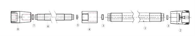
A. Packing Setup for 2.1 mm ID Columns
- 4.6 mm ID slurry reservoir (1×)
- End fitting for 4.6 mm column
- PEEK sealing ring, 0.25 in OD
- Adapter: 4.6 mm reservoir → 2.1 mm column
- ETFE sealing ring
- Column body, PEEK, 2.1 mm ID
- PEEK frit, 2 µm
- End fitting for 2.1 mm column
This assembly transitions slurry from a larger reservoir into a narrow‑ID body using the specified adapter. The 2 µm frit ensures proper support for typical silica particles (2–5 µm).
Packing reservoir and PEEK column hardware sketch for 2.1 mm ID columns.
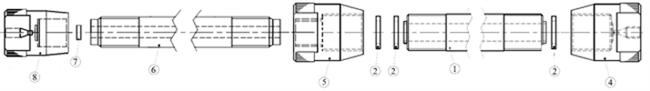
B. Packing Setup for 4.6 mm ID Columns
- 7.5 mm ID slurry reservoir (1×)
- PEEK sealing rings / frit spacers (3×)
- End fitting for 7.5 mm ID column
- Adapter: 7.5 mm reservoir → 4.6 mm column
- Column body, PEEK, 4.6 mm ID
- PEEK frit, 2 µm (requires two for a fully packed column)
- End fitting for 4.6 mm column (two required)
This is the most common PEEK hardware size and supports a wide array of silica‑based phases typically used for analytical HPLC.
Packing reservoir and PEEK column hardware for 4.6 mm ID columns.
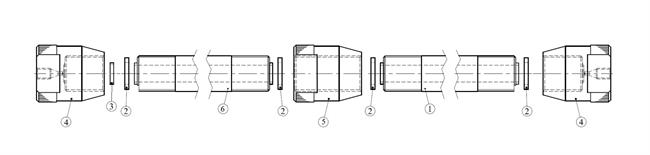
C. Packing Setup for 7.5 mm ID Columns
- 7.5 mm ID slurry reservoir
- PEEK sealing ring / frit spacer
- PEEK frit, 5 µm
- End fitting for 7.5 mm ID column
- Adapter: 7.5 mm reservoir → 7.5 mm column
- Column body, PEEK, 7.5 mm ID
The larger frit porosity (5 µm) aligns with typical prep‑scale silica particle sizes and reduces backpressure during packing.
Packing reservoir and PEEK column hardware for 7.5 mm ID columns.
Important Operational Notes
- Always maintain vertical orientation during slurry filling and inversion.
- Never exceed 300 bar packing pressure.
- Use only specified sealing rings; do not substitute frits at reservoir junctions.
- Follow the packing material manufacturer’s recommendations for slurry solvent, concentration, degassing, and vibration/sonication parameters.